
Abstract
Water scarcity and tightening discharge regulations are forcing municipalities and industrial operators to treat wastewater as a recoverable resource rather than a liability. The 浸漬膜モジュール has emerged as a core technology enabling this transition, delivering consistent effluent quality suitable for direct reuse or downstream reverse osmosis polishing.
At the heart of these systems is ultrafiltration (UF) membrane technology — a proven physical barrier capable of removing suspended solids, bacteria, protozoa, and colloidal turbidity in a single pass. Unlike conventional clarification, submerged UF produces effluent with turbidity routinely below 0.2 NTU and TSS near zero, regardless of feed water variability.
This article covers the operating principles of submerged membrane modules, critical performance parameters including flux and transmembrane pressure (TMP), the pretreatment and cleaning protocols that govern membrane service life, and the industrial and municipal application scenarios where these systems deliver measurable ROI. Whether you are evaluating a membrane bioreactor (MBR) upgrade or designing a tertiary polishing stage for water reuse compliance, this guide provides the technical framework to make an informed procurement decision.
1. How a Submerged Membrane Module Works in a Wastewater Treatment System
1.1 Filtration Mechanism of Submerged Ultrafiltration Membrane
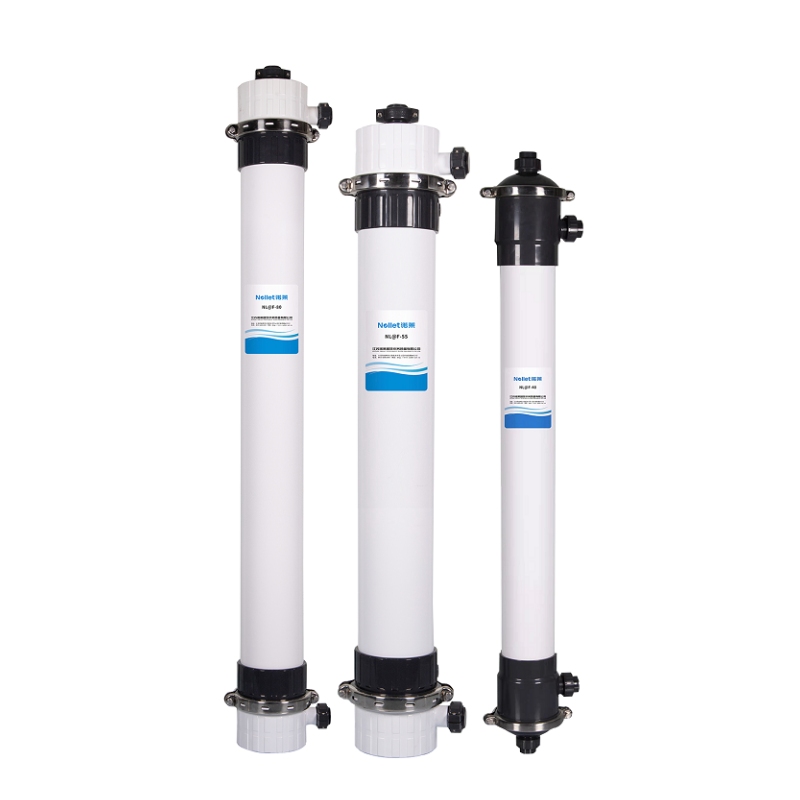
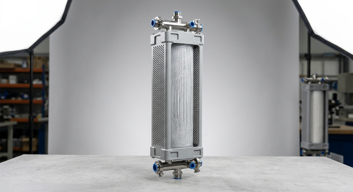
A submerged 超濾過膜 operates on a pressure-driven size exclusion principle, but its configuration distinguishes it from pressurized external modules. The membrane assembly is immersed directly in the feed tank or bioreactor, and permeate is extracted by applying a low vacuum — typically 10–40 kPa — to the permeate side of the membrane. This suction-driven mechanism eliminates the need for high-pressure feed pumps, significantly reducing energy consumption compared to side-stream configurations.
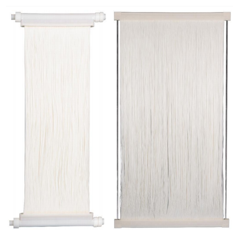
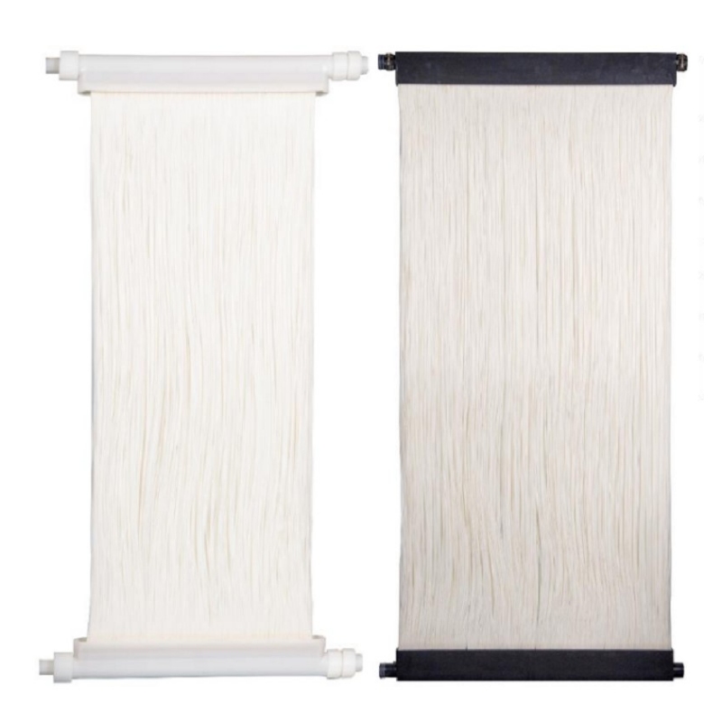
Most submerged modules employ hollow fiber membranes with a nominal pore size of 0.01–0.1 µm, positioned within the UF range. Two flow path configurations exist:
- Outside-in flow: Feed water contacts the outer surface of the fiber; permeate travels inward through the pore structure to the fiber lumen. This is the dominant configuration for submerged systems because the outer surface is directly accessible for air scouring during fouling control.
- Inside-out flow: Feed enters the fiber lumen; less common in submerged designs but used in specific high-flux applications.
Membrane materials are predominantly PVDF (polyvinylidene fluoride) due to its chemical resistance, mechanical strength, and hydrophilicity after surface modification. PES (polyethersulfone) is used in lower-fouling applications where enhanced permeability is prioritized.
The physical barrier mechanism — not chemical disinfection — achieves log-4 or greater removal of クリプトスポリジウム, ジアルディア, and most bacterial pathogens, making submerged UF a reliable compliance tool for water reuse permits.
1.2 Integration with MBR and Conventional Treatment Trains
Submerged membrane modules integrate into treatment systems at two primary positions:
-
Within a Membrane Bioreactor (MBR): The module is submerged inside the aeration tank, combining biological treatment and solid-liquid separation in a single vessel. This eliminates secondary clarifiers, reduces plant footprint by 30–50%, and produces effluent with BOD < 5 mg/L and TSS < 1 mg/L.
-
Tertiary polishing stage: Positioned after conventional secondary treatment (activated sludge + clarifier), the submerged module acts as a final barrier before discharge or reuse distribution. This retrofit approach is cost-effective for upgrading existing plants to meet water reuse standards without rebuilding the biological treatment stage.
In both configurations, coarse screening (1–2 mm) upstream is mandatory to protect fiber integrity. Chemical dosing — coagulants such as ferric chloride or polyaluminum chloride — may precede the membrane tank to reduce colloidal loading and extend cleaning intervals.
2. Key Performance Parameters and Technical Specifications
| 加圧膜システム | Municipal MBR Application | Industrial Tertiary Polishing | High-Flux Reuse System |
|---|---|---|---|
| Membrane Material | PVDF | PVDF / PES | PVDF (hydrophilic modified) |
| Nominal Pore Size | 0.04 µm | 0.04–0.1 µm | 0.02–0.04 µm |
| Design Flux (LMH) | 15–25 | 20–35 | 30–45 |
| Operating TMP (kPa) | 10–25 | 15–35 | 20–40 |
| Module Configuration | Hollow fiber | Hollow fiber / Flat sheet | Hollow fiber |
| Chemical Resistance | pH 2–12, NaOCl ≤ 3,000 ppm | pH 1–13 | pH 2–12, NaOCl ≤ 5,000 ppm |
| CEB Interval | 30–60 min | 60–120 min | 30–45 min |
2.1 Flux, TMP, and Fouling Control
Sustainable flux — the permeate flow rate per unit membrane area (LMH) at which fouling remains reversible — is the primary design variable. Operating above the critical flux threshold causes irreversible cake layer formation, accelerating TMP rise and shortening membrane life. For municipal MBR applications, sustainable flux typically ranges from 15–25 LMH; industrial systems with lower MLSS concentrations can operate at 25–40 LMH.
Fouling control relies on three mechanisms:
- Coarse bubble aeration: Air introduced below the membrane bundle creates turbulent crossflow, shearing the fouling layer from fiber surfaces. Specific aeration demand per membrane area (SADm) of 0.3–0.5 Nm³/m²·h is standard for hollow fiber modules.
- Backwash cycles: Periodic reversal of permeate flow (1–2 minutes every 8–15 minutes) dislodges pore-blocking foulants. Backwash flux is typically 1.5–2× the operating flux.
- Chemically Enhanced Backwash (CEB): NaOCl (200–500 mg/L) or citric acid solution is introduced during backwash every 24–72 hours to dissolve organic and inorganic foulants before they consolidate into irreversible fouling.
TMP trending is the primary operational indicator: a TMP increase exceeding 1 kPa/day signals the need for CEB or clean-in-place (CIP) intervention.
2.2 Effluent Quality Standards for Water Reuse
Submerged UF systems consistently achieve:
- Turbidity: < 0.2 NTU (target); < 0.1 NTU achievable under stable operation
- TSS: < 1 mg/L
- SDI15: < 3 (suitable as RO pre-treatment feed)
- Pathogen removal: ≥ 4-log クリプトスポリジウム, ≥ 4-log bacteria
These outputs align with the compliance thresholds of major water reuse frameworks:
- EU Regulation 2020/741: Class A reclaimed water requires turbidity < 1 NTU and E. coli < 10 CFU/100 mL — both achievable post-UF with UV or chlorination polishing.
- US EPA 2012 Guidelines for Water Reuse: UF qualifies as an approved treatment barrier for unrestricted urban reuse.
- ISO 20761: Provides the test methodology for UF membrane integrity verification, including pressure decay testing.
3. Operating Factors That Affect Filtration Performance
3.1 Feed Water Quality and Pretreatment Requirements
Feed water characteristics directly determine sustainable flux, cleaning frequency, and ultimately membrane service life. Three parameters require careful upstream management:
- TSS and MLSS concentration: In MBR applications, mixed liquor suspended solids above 12,000 mg/L significantly increase fouling propensity. Most submerged module manufacturers specify optimal MLSS between 6,000–10,000 mg/L.
- Oil and grease (O&G): Concentrations above 50 mg/L cause rapid hydrophobic fouling on PVDF surfaces. Oil-water separation upstream is mandatory for food processing or petroleum-related wastewater.
- BOD and surfactant loading: High surfactant concentrations reduce surface tension, promoting foam formation in the aeration tank and destabilizing the air-scouring pattern. Coagulant pre-dosing (10–30 mg/L FeCl₃) reduces colloidal BOD and improves filterability index.
Mechanical pretreatment using 1–2 mm fine screens is non-negotiable. Hair, fiber, and debris larger than the screen aperture will wrap around hollow fibers, causing localized blockages that cannot be removed by chemical cleaning.
3.2 Aeration Rate, Temperature, and Chemical Cleaning Protocol
Temperature affects both water viscosity and biological activity. A 10°C decrease in feed water temperature increases viscosity by approximately 25%, directly reducing flux at constant TMP. Operators must either reduce flux setpoints in winter or accept higher TMP operation — the latter risks accelerated fouling. Flux correction factors (typically 1.025–1.03 per °C) should be built into system design for climates with significant seasonal variation.
SADm optimization balances fouling control against energy cost. Under-aeration allows cake layer consolidation; over-aeration wastes energy and can cause fiber fatigue over time. Optimal SADm is determined during commissioning based on site-specific MLSS and flux targets.
CIP protocol for long-term membrane integrity:
- Alkaline CIP: 500–2,000 mg/L NaOCl at pH 11–12, soak 2–4 hours — targets biofouling and organic matter
- Acid CIP: 0.2–0.5% citric acid or 0.5% oxalic acid — targets inorganic scaling (calcium carbonate, iron hydroxide)
- Frequency: Typically every 3–6 months under normal operation; more frequent if TMP recovery after CEB is insufficient
Properly executed CIP restores membrane permeability to > 90% of initial values and is the primary determinant of achieving 7–10 year membrane service life.
4. Industrial and Municipal Application Scenarios
4.1 Wastewater Reuse in Industrial Processes
Industrial water reuse represents one of the highest-value applications for submerged membrane modules, driven by both water cost reduction and regulatory compliance pressure:
- Textile industry: Dyeing and finishing processes generate high-color, high-TSS effluent. Submerged UF removes suspended dye particles and fiber fragments, producing reclaimed water suitable for process reuse — reducing fresh water consumption by 40–60%.
- Food and beverage: Wastewater with high BOD (500–3,000 mg/L) and FOG content requires biological pre-treatment before membrane filtration. MBR systems combining anaerobic digestion and submerged UF achieve discharge compliance while enabling cooling tower makeup water reuse.
- Semiconductor and electronics: Ultra-pure cooling water recycling demands SDI < 3 as a prerequisite for downstream RO/EDI treatment. Submerged UF consistently delivers this specification, reducing ultra-pure water production costs.
The ROI case is direct: avoided discharge fees, reduced freshwater procurement costs, and eliminated compliance penalties typically deliver payback periods of 3–5 years for industrial installations in water-stressed regions.
4.2 Municipal Reclaimed Water and Indirect Potable Reuse
Municipal MBR plants using submerged membrane modules now operate at capacities ranging from 0.5 MLD (small community systems) to 500+ MLD (metropolitan scale). The submerged module configuration is preferred at municipal scale because its modular architecture allows capacity expansion by adding membrane cassettes without redesigning the tank infrastructure.
For indirect potable reuse (IPR), submerged UF serves as the critical pre-treatment barrier ahead of reverse osmosis and advanced oxidation. The UF permeate’s low SDI (< 3) and near-zero TSS protect RO membranes from particulate fouling, extending RO element life and reducing replacement costs by an estimated 20–30%.
Regulatory acceptance of UF as a validated treatment barrier — confirmed through ongoing integrity testing per ISO 20761 and ASTM D6908 — has accelerated municipal adoption in water-stressed regions including the Middle East, Australia, Singapore, and the US Southwest.
FAQ
Q1: What pore size of submerged ultrafiltration membrane is required to meet water reuse discharge standards?
A nominal pore size of 0.04 µm (40 nm) is the industry standard for water reuse applications. This pore size achieves ≥ 4-log removal of クリプトスポリジウム および ジアルディア (which require < 1 µm exclusion) and effectively removes bacteria. For applications requiring SDI < 3 as RO pre-treatment feed, 0.02–0.04 µm is recommended. Pore sizes up to 0.1 µm are acceptable for non-potable industrial reuse where pathogen removal is not the primary compliance requirement.
Q2: How often does a submerged membrane module need chemical cleaning, and what does it cost operationally?
Routine CEB (chemically enhanced backwash) runs every 24–72 hours using dilute NaOCl or citric acid and adds minimal chemical cost — typically USD 0.01–0.03 per m³ of permeate. Full CIP is required every 3–6 months, with chemical and labor costs of approximately USD 500–2,000 per cleaning event depending on system size. Total chemical cleaning costs represent less than 5% of total operating cost for most installations, with energy (aeration) being the dominant OPEX driver.
Q3: Can a submerged membrane module handle high-TSS industrial wastewater without frequent clogging?
Yes, with appropriate pretreatment. Submerged hollow fiber modules are designed for mixed liquor TSS up to 10,000–15,000 mg/L in MBR configurations. For feed streams above this threshold or with high fiber/debris content, 1–2 mm fine screening and coagulant pre-dosing are mandatory. Flat-sheet submerged modules offer an alternative for very high-solids applications, as their open channel geometry is less susceptible to clogging than hollow fiber bundles.
結論
The submerged membrane module has proven itself as a technically reliable and commercially scalable solution for wastewater treatment and water reuse across both municipal and industrial sectors. Its ability to deliver turbidity < 0.2 NTU, TSS near zero, and ≥ 4-log pathogen removal — consistently and at low operating pressure — makes it the preferred physical barrier technology for reuse permit compliance.
Key selection criteria for procurement teams should focus on: membrane material (PVDF for chemical resistance and longevity), nominal pore size (0.04 µm for regulated reuse), sustainable flux range matched to site MLSS conditions, and manufacturer support for CIP protocol validation. Modular cassette architecture ensures that capacity can scale alongside operational demand without capital-intensive tank reconstruction.
For facilities facing water discharge costs, freshwater procurement expenses, or tightening reuse regulations, the submerged membrane module delivers a measurable return on investment within 3–5 years in most scenarios. Contact our technical team to discuss membrane module specifications, pilot testing options, and system integration support tailored to your wastewater treatment objectives.