
Abstract
MBR membraanmodule selection is one of the most consequential decisions in wastewater treatment plant design. The wrong configuration can mean chronic fouling, elevated energy bills, premature membrane replacement, and effluent quality failures—all of which translate directly into capital write-downs and regulatory exposure.
This guide provides procurement engineers, plant designers, and technical consultants with a structured framework for evaluating the two dominant MBR membrane module configurations: hollow fiber and flat sheet. It maps each configuration to specific wastewater characteristics, operational parameters, and compliance requirements. Whether you are designing a new municipal reuse facility, upgrading an industrial effluent system, or evaluating lifecycle costs for a long-term service contract, the specification logic presented here gives you a defensible, data-anchored starting point.
The analysis draws on established flux benchmarks, material performance data, and international regulatory standards to ensure that configuration decisions align with both technical and commercial objectives.
1. Understanding MBR Membrane Module Configurations
1.1 Hollow Fiber MBR Modules
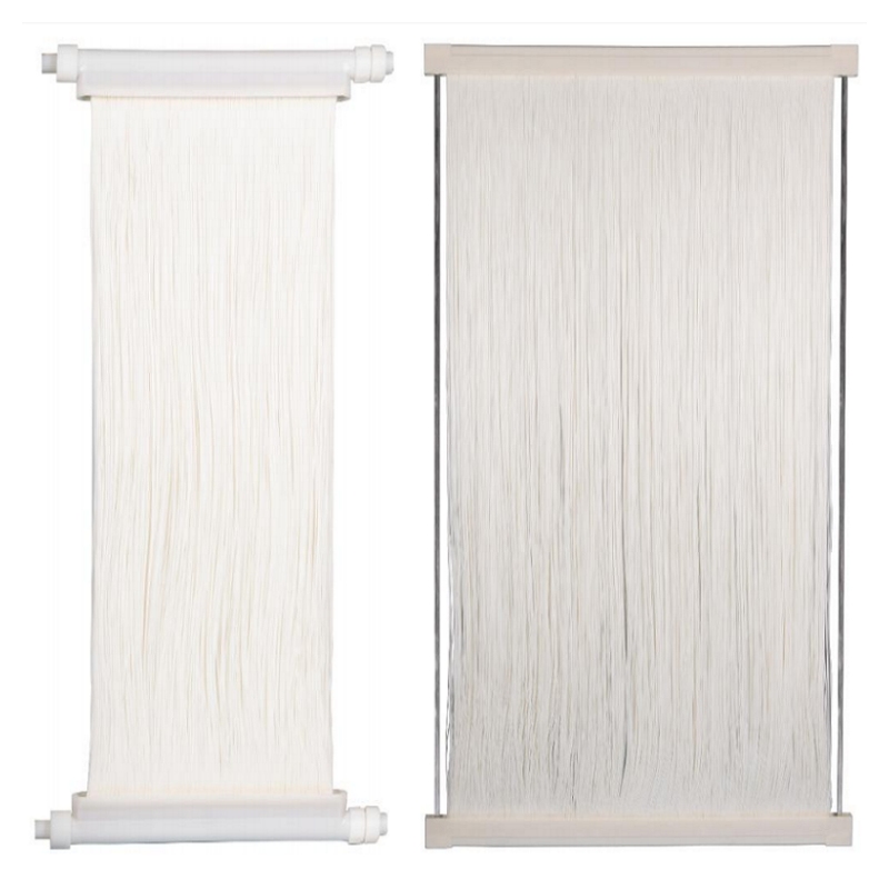
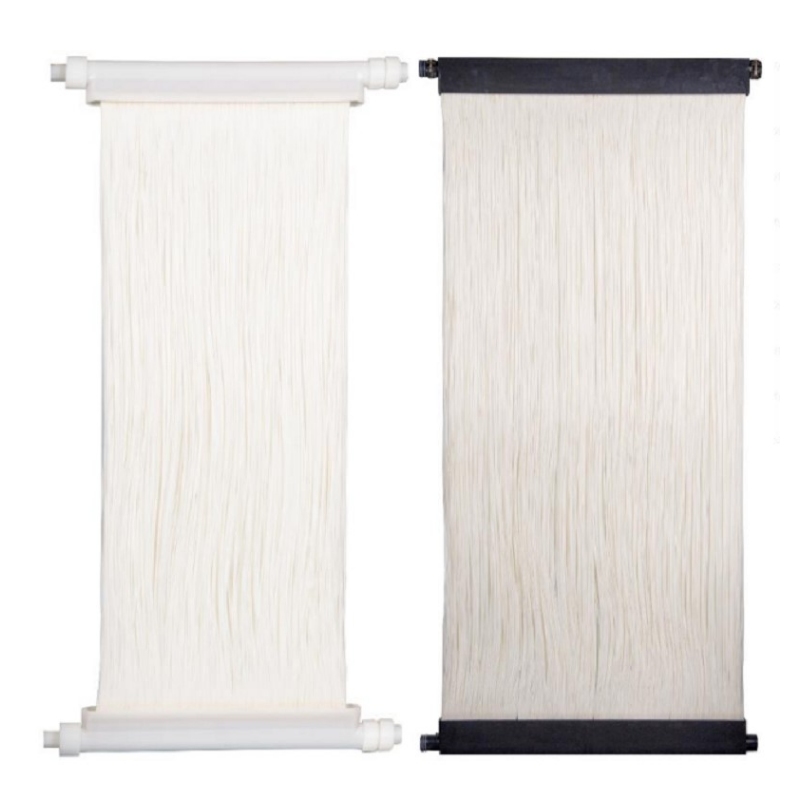
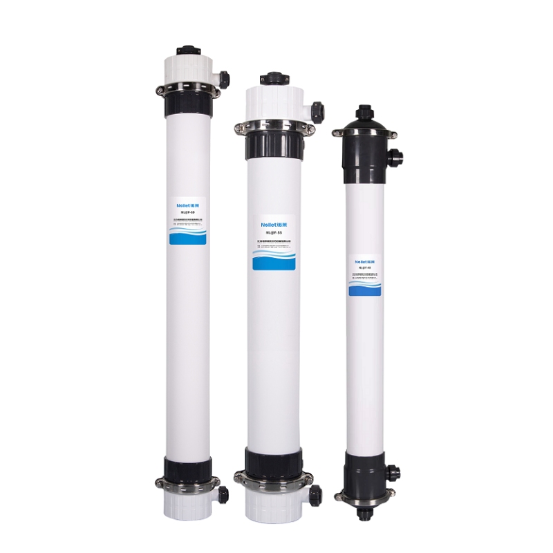
Hollow fiber MBR modules consist of thousands of fine, self-supporting membrane filaments—typically 0.5 to 2.0 mm in outer diameter—bundled into a module housing and submerged directly in the bioreactor. The fiber wall acts as the filtration barrier, with permeate drawn from the inside (inside-out flow) or outside (outside-in flow) of each filament under slight vacuum.
Structural advantages include an exceptionally high packing density, commonly ranging from 150 to 400 m²/m³, which minimizes the physical footprint of the membrane tank for a given treatment capacity. This makes hollow fiber the preferred choice for municipal plants operating under land constraints.
Water quality suitability centers on moderate-strength influents with mixed liquor suspended solids (MLSS) concentrations of 8–12 g/L. Hollow fiber modules perform reliably when influent TSS and oil/grease levels are controlled, as fiber bundles are susceptible to irreversible clogging from fibrous debris, hair, and high-viscosity sludge.
Typical flux parameters operate in the range of 15–30 LMH (liters per square meter per hour) under normal conditions, with peak design flux reaching 40 LMH in short-duration demand events. Coarse-bubble aeration scouring beneath the module bundle is essential for fouling control, and aeration intensity directly governs energy consumption per cubic meter treated.
1.2 Flat Sheet MBR Modules
Flat sheet MBR modules use planar membrane panels—typically 500 to 1,000 mm in height—mounted in parallel cassette frames and submerged in the aeration tank. Permeate passes through the membrane surface into internal drainage channels and is extracted via header piping.
The primary structural advantage is mechanical robustness. Individual panels are replaceable without removing the entire cassette, reducing maintenance downtime and module replacement costs. The open-channel geometry between panels resists blockage by fibrous materials and coarse suspended solids, making flat sheet configurations significantly more tolerant of poorly screened or high-viscosity influents.
Anti-fouling performance is enhanced by the larger inter-panel spacing (6–10 mm), which allows rising air bubbles to generate effective cross-flow shear across the membrane surface. This geometry sustains stable operation at MLSS concentrations of 10–15 g/L, and in some industrial applications up to 18 g/L.
High-suspended-solids scenario adaptability makes flat sheet the configuration of choice for food processing effluent, municipal sludge reject water, and pharmaceutical wastewater streams where COD concentrations exceed 2,000 mg/L and particle size distribution is unpredictable.
2. Key Technical Parameters for MBR Module Specification
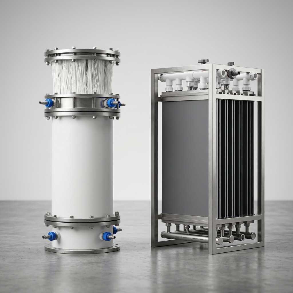
The table below provides a direct comparison of the three principal MBR membrane configurations against the parameters most relevant to procurement specifications.
| Parameter | Hollow Fiber | Flat Sheet | Tubular |
|---|---|---|---|
| Nominal Pore Size (μm) | 0.03–0.4 (UF/MF) | 0.08–0.4 (MF) | 0.05–0.3 (UF) |
| Design Flux (LMH) | 15–30 | 10–25 | 40–120 |
| Operating TMP (kPa) | 10–40 | 5–30 | 50–300 |
| Recommended MLSS (g/L) | 8–12 | 10–18 | 5–10 |
| Packing Density (m²/m³) | 150–400 | 80–150 | 50–100 |
| Cleaning Method | Backflush + CIP | Relaxation + CIP | CIP + high-velocity flush |
| Typical Cleaning Interval | 8–24 hr (maintenance) | 10–30 min (relaxation) | Application-dependent |
2.1 Membrane Material & Pore Size Standards
PVDF (polyvinylidene fluoride) dominates MBR membrane manufacturing due to its chemical resistance to chlorine-based cleaning agents (sodium hypochlorite at 500–2,000 ppm), wide pH tolerance (2–11), and structural integrity under repeated hydraulic stress cycles. PES (polyethersulfone) offers lower manufacturing cost and good hydrophilicity but exhibits reduced resistance to oxidative cleaning agents, limiting its practical service life in high-fouling applications.
For reuse-grade applications, ultrafiltration membranes with nominal pore sizes of 0.03–0.1 μm provide the pathogen log-reduction values required under NSF/ANSI 61 for indirect potable reuse and ISO 11591 for membrane characterization. Microfiltration membranes (0.1–0.4 μm) are acceptable for non-potable reuse and industrial discharge compliance but require downstream UV or chlorination to meet WHO Guidelines for water reuse.
2.2 Flux, TMP & Fouling Control
The critical flux concept is central to sustainable MBR operation: operating below the critical flux threshold prevents irreversible fouling cake formation on the membrane surface. For most municipal hollow fiber installations, critical flux falls between 20–25 LMH; exceeding this threshold—even transiently—accelerates TMP rise and shortens chemical cleaning intervals.
TMP monitoring should trigger a maintenance clean when values exceed 25–35 kPa for hollow fiber and 15–25 kPa for flat sheet systems. Recovery cleaning (CIP) is initiated when TMP approaches 50–60% of the manufacturer’s maximum rated pressure.
Aeration intensity (specific aeration demand per membrane area, SAD_m) typically ranges from 0.3 to 0.6 Nm³/h/m² for hollow fiber and 0.15 to 0.4 Nm³/h/m² for flat sheet, directly linking fouling control strategy to the plant’s energy consumption per cubic meter of permeate produced.
3. Application Scenarios & Configuration Matching
3.1 Municipal Wastewater & Water Reuse
Municipal influent typically presents BOD₅ of 150–300 mg/L, TSS of 200–400 mg/L, and ammonia nitrogen of 30–60 mg/L. These moderate-strength characteristics favor hollow fiber modules for their high packing density, lower capital cost per m², and well-established operational protocols in large-scale facilities.
For water reuse applications governed by ISO 16075 (irrigation reuse) or local Title 22 equivalents, MBR effluent consistently achieves TSS <1 mg/L, turbidity <0.2 NTU, and 4-log pathogen reduction—meeting Class A reuse standards without tertiary filtration. This positions MBR as a compact, single-step upgrade path for municipal plants targeting recycled water revenue.
Configuration selection logic: specify hollow fiber for flows >5,000 m³/day where footprint efficiency is the primary driver; consider flat sheet for smaller municipal plants (<2,000 m³/day) where operational simplicity and reduced screening requirements lower the total installed cost.
3.2 Industrial & High-Strength Wastewater
Industrial wastewater from food processing, pharmaceutical manufacturing, and specialty chemicals presents COD concentrations of 2,000–15,000 mg/L, elevated fats/oils/grease (FOG), and variable pH—conditions that challenge hollow fiber geometry through accelerated pore plugging and fiber bundle clogging.
Flat sheet modules are the technically preferred configuration for these streams. The replaceable-panel architecture allows targeted membrane replacement when individual panels foul beyond recovery, avoiding full cassette changeout costs. Anti-fouling priority outweighs the lower packing density penalty because industrial plants typically operate smaller footprints with higher value-per-cubic-meter treatment economics.
Maintenance cost trade-off: flat sheet panel replacement costs 15–25% more per m² than hollow fiber element replacement, but the extended cleaning intervals and lower aeration energy at high MLSS concentrations can offset this premium within 18–24 months of operation in high-COD environments.
4. Procurement & Compliance Considerations
4.1 Regulatory Standards & Certifications
Export projects and publicly tendered municipal contracts increasingly require documented compliance with international certification frameworks. Key certifications to verify during supplier qualification include:
- NSF/ANSI 61: Material safety for drinking water contact components—mandatory for potable reuse applications in North American markets.
- CE Marking (EU Machinery Directive / Pressure Equipment Directive): Required for MBR systems sold into European Union projects.
- WHO Guidelines for Drinking-Water Quality (4th Edition): Referenced in World Bank and ADB-funded infrastructure projects across Asia, Africa, and Latin America.
- ISO 9001 / ISO 14001: Quality management and environmental management system certification for the manufacturing facility—increasingly specified in public tender evaluation criteria.
Procurement teams should request third-party test reports confirming nominal pore size, clean water permeability, and tensile strength for each module batch, not just manufacturer datasheets.
4.2 Total Cost of Ownership (TCO) Evaluation
Initial capital cost represents only 30–40% of the 10-year TCO for an MBR membrane system. The remaining cost structure breaks down as follows:
- Energy (aeration + permeate pumping): 40–55% of TCO over a 10-year period.
- Chemical cleaning consumables: 5–10%.
- Membrane replacement (at 5–8 year intervals): 15–25%.
- Labor and maintenance: 10–15%.
A 5–8 year membrane lifespan is achievable under proper operating conditions; aggressive fouling, oxidative cleaning overuse, or sustained above-critical-flux operation can reduce effective life to 3–4 years. Procurement contracts should include guaranteed flux performance clauses and define the conditions under which warranty replacement applies.
For modular procurement strategy, specifying a common cassette frame standard across multiple plant phases enables future membrane element upgrades without structural tank modifications—a significant lifecycle cost advantage.
Veelgestelde vragen
1. What is the typical lifespan of an MBR membrane module, and what factors accelerate degradation?
Under well-managed operating conditions—consistent TMP monitoring, scheduled maintenance cleans, and controlled MLSS concentrations—MBR membrane modules achieve a service life of 7–10 years for PVDF hollow fiber and 8–12 years for flat sheet panels. Primary degradation accelerators include excessive hypochlorite cleaning concentration (>3,000 ppm NaOCl), sustained above-critical-flux operation, and physical damage from unscreened fibrous debris entering the bioreactor.
2. How do I determine the required membrane area for my target daily flow rate and effluent quality?
Calculate required membrane area using: A (m²) = Q (m³/day) ÷ (J_design × 24), where J_design is the sustainable design flux in LMH. Apply a peaking factor of 1.3–1.5 to account for diurnal flow variation and fouling allowance. For a 5,000 m³/day plant at 20 LMH design flux: A = 5,000 ÷ (20 × 24) = 10.4 m² per unit—then size module count accordingly with 15–20% installed redundancy.
3. Can hollow fiber and flat sheet modules be retrofitted into an existing MBR tank without full system redesign?
Retrofitting is feasible if the existing tank geometry accommodates the new module cassette dimensions and the aeration grid can be reconfigured. Hollow-fiber-to-flat-sheet conversion typically requires wider inter-cassette spacing and modified aeration headers. Engage the membrane supplier’s engineering team for a tank survey before committing to a retrofit specification, as structural modifications can represent 20–35% of the total retrofit cost.
Conclusie
Selecting the right MBR membrane module configuration is not a single-variable decision. It requires systematic evaluation of influent characteristics, target effluent quality, available footprint, energy cost structure, and long-term maintenance strategy. Hollow fiber modules deliver the highest packing density and lowest capital cost per m² for moderate-strength municipal applications; flat sheet modules provide superior fouling resilience and operational flexibility for high-strength industrial streams.
A specification process anchored in verified flux data, material compatibility with your cleaning chemistry, and documented regulatory compliance reduces procurement risk and protects plant performance over the full membrane lifecycle. Engage suppliers who provide third-party certified performance data, offer standardized cassette frames for future upgrade compatibility, and can demonstrate reference installations in comparable wastewater matrices.
The right MBR membrane module configuration is the one that meets your effluent targets at the lowest verified 10-year TCO—not simply the lowest unit price on the quotation sheet.