
Abstract
Reverse osmosis membrane technology represents the gold standard in water purification, enabling the removal of dissolved salts, heavy metals, pathogens, and micropollutants at rejection rates exceeding 99%. The mechanism is elegantly precise: by applying hydraulic pressure greater than the natural osmotic pressure of the feed water, water molecules are forced through a semi-permeable membrane while contaminants are retained and discharged as concentrate.
For procurement engineers and system designers operating in sectors ranging from municipal water treatment to semiconductor fabrication, understanding the underlying science of RO membranes is not academic—it is commercially critical. Membrane selection directly impacts capital expenditure, operating costs, system recovery rates, and regulatory compliance. A misspecified membrane leads to premature fouling, elevated energy consumption, and costly downtime.
This article provides a structured, technically grounded walkthrough of how RO membranes filter water—from the physics of osmotic pressure reversal to the four-layer composite architecture, the two-stream output model, key performance parameters, and applicable compliance standards. Whether you are evaluating suppliers, designing a new system, or optimizing an existing installation, this guide delivers the specification-level insight required for informed decision-making.
1. The Core Science: How Reverse Osmosis Membrane Works
1.1 Osmosis vs. Reverse Osmosis: The Pressure-Driven Mechanism
In natural osmosis, water migrates spontaneously across a semi-permeable membrane from a region of low solute concentration to one of high solute concentration, driven by the chemical potential gradient. This movement continues until equilibrium is reached—a state defined by the osmotic pressure of the solution, typically measured in bar or psi.
Reverse osmosis inverts this process entirely. By applying hydraulic pressure that exceeds the osmotic pressure of the feed water—commonly 150–600 psi (10–41 bar) for brackish water and up to 1,200 psi (83 bar) for seawater desalination—water molecules are compelled to flow in the thermodynamically unfavorable direction: from high-concentration feed to low-concentration permeate.
The selectivity of this process depends on semi-permeable membrane selectivity: the membrane’s pore structure, typically with an effective separation threshold of 0.0001 microns, allows water molecules (diameter ~0.28 nm) to pass while physically excluding hydrated ions, organic molecules, and biological contaminants. Sodium chloride, for instance, is rejected not solely by size exclusion but by a combination of charge repulsion and solution-diffusion transport mechanisms within the dense polyamide active layer.
This pressure-driven selectivity is what distinguishes RO from microfiltration or ultrafiltration—it operates at the ionic scale, making it the only membrane technology capable of desalination.
1.2 The Four-Layer Structure of an RO Membrane Element
Industrial RO membrane elements are not single-layer films—they are precision-engineered composites designed to balance permeability, mechanical strength, and chemical resistance.
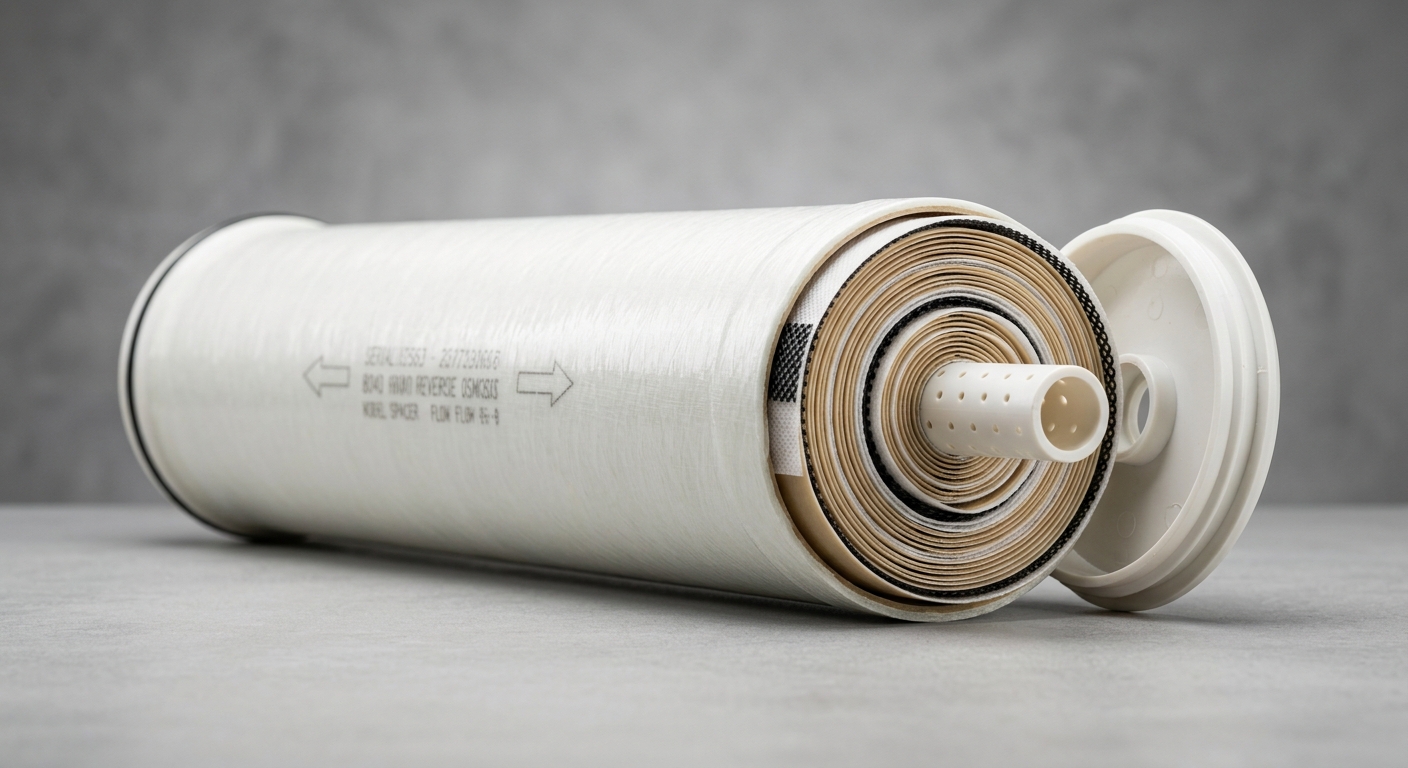
The standard polyamide thin-film composite (TFC) element consists of four functional layers:
- Polyester fabric backing – Provides structural support and dimensional stability under high operating pressures.
- Polysulfone support layer (~40–60 µm) – A microporous intermediate layer that provides mechanical support to the ultrathin active layer while maintaining high water flux.
- Polyamide active layer (~0.2 µm) – The functional separation layer, formed via interfacial polymerization. This is where salt rejection and water permeability are determined. Crosslink density in this layer governs the trade-off between flux and rejection.
- Protective coating (optional) – Some elements include a surface coating to improve fouling resistance or chlorine tolerance.
In commercial deployments, these layers are assembled into a spiral-wound configuration: membrane sheets are wound around a central permeate collection tube with feed spacers and permeate spacers interleaved. This geometry maximizes active membrane area per unit volume—a standard 8-inch diameter, 40-inch long (8040) element contains approximately 37–41 m² of active surface area.
The TFC architecture is the industry benchmark, offering superior salt rejection (>99%) and flux performance compared to older cellulose triacetate (CTA) membranes, though CTA retains niche utility in chlorinated feed water applications due to its moderate chlorine tolerance.
2. Step-by-Step: The RO Water Filtration Process
2.1 Pre-Treatment, Feed Water Flow & Rejection Mechanism
An RO system does not begin at the membrane—it begins at pre-treatment, which is critical to protecting membrane integrity and sustaining long-term performance.
Pre-treatment sequence typically includes:
- Sediment filtration (5–20 µm) to remove suspended solids
- Activated carbon filtration to eliminate chlorine and chloramines, which degrade polyamide TFC membranes
- Antiscalant dosing to prevent carbonate, sulfate, and silica scaling on the membrane surface
- pH adjustment to optimize operating conditions and minimize scaling potential
Once pre-treated, feed water enters the membrane pressure vessel under applied hydraulic pressure. At the membrane surface, water molecules diffuse through the polyamide active layer into the permeate channel. Dissolved ions, organic compounds, and colloids are physically and electrostatically rejected, accumulating in the boundary layer near the membrane surface—a phenomenon known as concentration polarization.
The Salt Rejection Rate (SRR) is the primary performance indicator, defined as:
SRR (%) = [1 – (Cp / Cf)] × 100
Where Cp = permeate concentration and Cf = feed concentration. High-performance TFC membranes achieve SRR values of 98–99.7% for NaCl under standardized test conditions (typically 250 ppm NaCl, 77°F/25°C, 225 psi/15.5 bar).
2.2 Permeate vs. Concentrate: Two-Stream Output Explained
Every RO system produces two output streams:
- Permeate (product water): The purified stream that has passed through the membrane. This is the target output—low in TDS, free of biological contaminants, and suitable for downstream use.
- Concentrate (reject/brine): The stream carrying rejected contaminants at elevated concentration. This must be managed for disposal, recirculation, or further treatment.
The Recovery Rate defines the ratio of permeate produced to feed water consumed:
Recovery Rate (%) = (Qp / Qf) × 100
Typical recovery rates range from 50–75% for brackish water systems and 35–45% for seawater RO. Higher recovery rates reduce water waste and operating costs but increase concentration polarization and scaling risk, requiring careful system design and antiscalant management. Energy recovery devices (ERDs) are commonly deployed in high-pressure seawater systems to recapture hydraulic energy from the concentrate stream, significantly reducing OPEX.
RO Membrane Key Performance Parameters Comparison
| Parametr | Brackish Water TFC | Seawater TFC | Low-Pressure TFC | CTA Membrane |
|---|---|---|---|---|
| Salt Rejection Rate (%) | 99.0–99.7% | 99.6–99.8% | 97.0–99.0% | 93.0–97.0% |
| Operating Pressure (psi/bar) | 150–600 / 10–41 | 800–1,200 / 55–83 | 75–150 / 5–10 | 200–400 / 14–28 |
| Permeate Flow Rate (GPD) | 8040: 10,000–12,000 | 8040: 6,000–8,000 | 8040: 12,000–14,000 | 8040: 7,000–9,000 |
| Max Feed Temperature (°C) | 45°C | 45°C | 45°C | 35°C |
| pH Tolerance Range | 2–11 (operating) | 2–11 (operating) | 3–10 (operating) | 4–8 (operating) |
| Membrane Material | Polyamide TFC | Polyamide TFC | Polyamide TFC | Cellulose Triacetate |
3. RO Membrane Specifications & Compliance Standards
3.1 Critical Technical Parameters for Industrial & Commercial Selection
Selecting the correct RO membrane for an industrial or commercial application requires evaluation beyond basic salt rejection claims. Key technical parameters include:
- MWCO (Molecular Weight Cut-Off): For RO membranes, effective MWCO is typically <200 Daltons, enabling rejection of most dissolved organics, pharmaceuticals, and divalent ions. This distinguishes RO from nanofiltration (NF), which typically operates at 200–1,000 Da.
- Flux Rate (L/m²/h or GFD): Defines the volume of permeate produced per unit membrane area per unit time. Higher flux rates reduce the required membrane area for a given output but may accelerate fouling. Typical design flux values range from 10–25 L/m²/h depending on feed water quality.
- Operating Pressure Range: Must be matched to the feed water TDS and system pump specifications. Undersized pressure leads to inadequate rejection; oversized pressure accelerates membrane compaction.
- Silt Density Index (SDI) tolerance: Feed water SDI should be maintained below 5 (ideally <3) to prevent colloidal fouling. This directly informs pre-treatment design requirements.
3.2 Applicable Certifications & Industry Standards
For procurement teams sourcing membranes for regulated applications, certification compliance is non-negotiable:
- NSF/ANSI 58: The primary certification for RO systems used in drinking water applications in North America. Covers contaminant reduction claims, materials safety, and structural integrity. Specifying NSF/ANSI 58-certified membranes ensures regulatory defensibility.
- ISO 9001: Confirms that the manufacturer operates a certified quality management system—a baseline requirement for industrial procurement and auditable supply chains.
- FILMTEC / Hydranautics benchmark compliance: Leading OEM membranes from DuPont (FILMTEC) and Hydranautics set industry performance benchmarks. Specifying equivalent or superior performance to these references provides a reliable technical baseline when evaluating alternative suppliers.
- CE Marking / WRAS Approval: Required for systems deployed in European markets or UK water infrastructure projects.
4. Industrial & Commercial Application Scenarios
4.1 Key End-Use Markets and Water Quality Requirements
RO membrane performance requirements vary significantly across end-use sectors:
- Municipal Water Treatment: Requires consistent high recovery rates (65–75%), NSF/ANSI 58 compliance, and long service intervals to minimize operational disruption. Feed water TDS typically ranges from 500–3,000 ppm.
- Food & Beverage: Demands FDA-compliant materials, high flux stability, and compatibility with CIP (Clean-in-Place) chemical protocols. Brewery and dairy applications often require specific pH tolerance ranges.
- Semiconductor Manufacturing: Requires ultrapure water (UPW) production with resistivity >18 MΩ·cm. This demands multi-stage RO systems with EDI polishing, and membranes with extremely low extractable levels.
- Seawater Desalination: High-pressure operation (55–83 bar) with energy recovery systems. Membrane selection prioritizes boron rejection (often requiring second-pass RO at elevated pH) alongside sodium chloride rejection.
- Industrial Wastewater Reclaim: Variable feed quality with high fouling potential. Requires robust pre-treatment and membranes with enhanced fouling resistance coatings.
4.2 Total Cost of Ownership: Membrane Lifespan & Replacement Cycle
The purchase price of an RO membrane element represents only a fraction of its true cost of ownership. Procurement decisions must account for:
- Membrane fouling is the primary driver of performance degradation. Biofouling, scaling, and colloidal fouling progressively reduce flux and increase differential pressure. Effective pre-treatment and antiscalant programs are the most cost-effective fouling mitigation strategies.
- Cleaning frequency (CIP): Membranes requiring more than 1–2 CIP cycles per month indicate inadequate pre-treatment or membrane mismatch. Frequent chemical cleaning accelerates membrane aging and increases chemical OPEX.
- 3–5 year replacement cycle: Under proper operating conditions (SDI <3, no chlorine exposure, effective antiscalant dosing), high-quality TFC membranes maintain performance for 3–5 years. Premature replacement due to avoidable fouling is a significant hidden cost.
- OPEX reduction through energy-efficient membrane selection: Low-pressure, high-flux membranes can reduce pump energy consumption by 15–25% compared to conventional elements in comparable feed water conditions, delivering measurable lifecycle savings.
FAQ
1. What is the difference between a 4040 and 8040 RO membrane, and which is right for my system capacity?
The designations refer to membrane element dimensions: 4040 = 4-inch diameter, 40-inch length; 8040 = 8-inch diameter, 40-inch length. An 8040 element contains roughly 6–7× the active membrane area of a 4040 element and produces proportionally higher permeate flow (typically 10,000–12,000 GPD vs. 2,400–3,000 GPD for brackish water TFC). For commercial and industrial systems above 10 m³/h, 8040 elements are standard due to lower per-unit cost and reduced vessel count. 4040 elements suit smaller commercial systems, pilot testing, or space-constrained installations.
2. How do I verify the salt rejection rate and flux performance when sourcing RO membranes from a new supplier?
Request third-party test reports conducted under standardized conditions (ASTM D4194 or equivalent): 250 ppm NaCl, 77°F (25°C), 225 psi (15.5 bar), 15% recovery. Verify that test data is membrane-specific (not system-level) and request batch-level QC certificates. For critical applications, conduct independent verification testing on sample elements before full procurement. NSF/ANSI 58 certification provides additional assurance for drinking water applications.
3. What pre-treatment conditions are required to protect RO membrane lifespan in high-SDI or high-chlorine feed water?
For high-SDI feed water (SDI >5): implement dual-media filtration, ultrafiltration (UF) pre-treatment, and coagulation/flocculation to reduce colloidal loading before the RO stage. For chlorinated feed water: install activated carbon filtration or sodium metabisulfite (SMBS) dosing upstream of the RO to maintain free chlorine below 0.1 ppm—polyamide TFC membranes have zero chlorine tolerance and will suffer irreversible active layer degradation within hours of chlorine exposure. CTA membranes tolerate up to 1 ppm continuous chlorine but sacrifice rejection performance.
Konkluzja
Reverse osmosis membrane filtration operates on a precise physical-chemical principle: applied hydraulic pressure overcomes osmotic resistance to drive water molecules through a nanoscale polyamide active layer, achieving ionic-level separation that no other membrane technology can match at comparable scale and cost.
For procurement engineers and system designers, the critical takeaways are threefold. First, membrane architecture—specifically the TFC polyamide composite in spiral-wound configuration—defines the performance ceiling; material selection between TFC and CTA must be driven by feed water chemistry, not cost alone. Second, key parameters including salt rejection rate, flux rate, operating pressure, and MWCO must be matched to application-specific requirements, with NSF/ANSI 58 and ISO 9001 certifications serving as baseline compliance requirements for regulated markets. Third, total cost of ownership demands equal weight alongside unit price: a membrane that delivers 5-year service life under optimized pre-treatment conditions consistently outperforms a cheaper alternative requiring annual replacement.
Sourcing decisions that integrate technical specification rigor, supplier certification verification, and lifecycle cost modeling will consistently deliver superior system performance, regulatory compliance, and return on capital investment.