
Abstract
Industrial water scarcity and increasingly stringent discharge regulations have elevated wastewater reuse from a compliance option to a strategic operational imperative. Ultrafiltration (UF) membrane technology sits at the center of this transition, functioning as a precision separation barrier capable of removing suspended solids, colloidal particles, bacteria, and high-molecular-weight organics from complex effluent streams.
Unlike conventional clarification or media filtration, UF membranes deliver consistent, quantifiable effluent quality regardless of influent variability—a critical advantage for facilities targeting zero liquid discharge (ZLD) or reverse osmosis (RO) integration. For procurement engineers and water treatment plant managers, UF membranes represent both a standalone treatment solution for direct reuse applications and the most reliable pretreatment technology available for protecting downstream RO assets.
This article examines the separation mechanics, material configurations, operating parameters, and total cost of ownership associated with industrial-grade ultrafiltration membranes, providing the technical and commercial data points needed to support informed procurement decisions.
1. How Ultrafiltration Membranes Work in Wastewater Treatment
1.1 Membrane Separation Mechanism & Pore Size Fundamentals
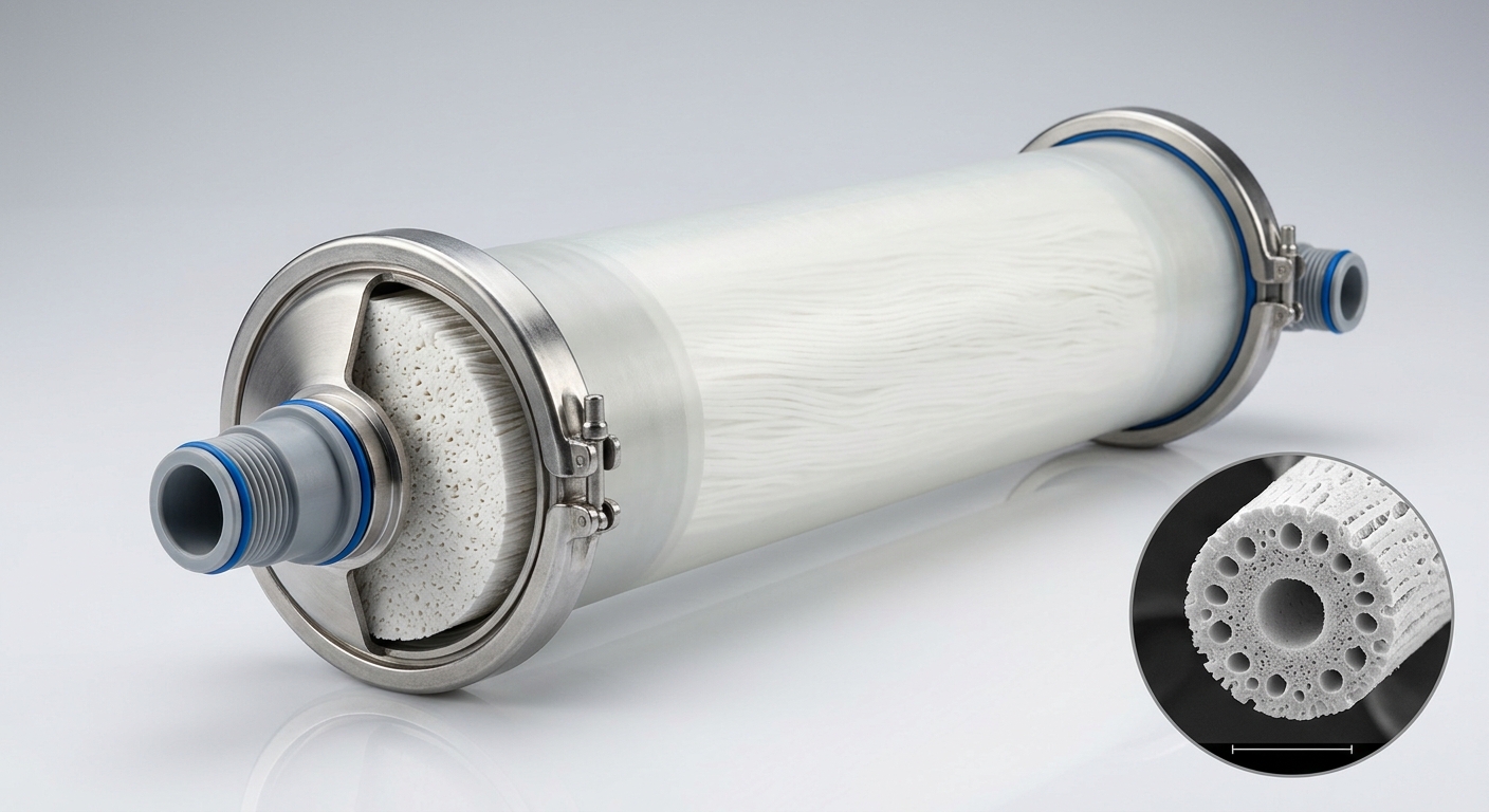
Ultrafiltration operates on a pressure-driven, size-exclusion principle. UF membranes feature nominal pore sizes in the range of 0.01–0.1 µm, positioning them between microfiltration (MF) at 0.1–10 µm and nanofiltration (NF) at 0.001–0.01 µm. This pore range enables selective rejection of:
- Suspended solids and turbidity-causing particles (>0.1 µm)
- Colloidal silica and organic colloids (0.01–0.1 µm)
- Bacteria and protozoa (typically 0.2–10 µm)
- Macromolecules such as proteins, polysaccharides, and humic substances (molecular weight cutoff: 1,000–500,000 Da)
Operating transmembrane pressures (TMP) for UF systems typically range from 0.5 to 3.0 bar in pressurized configurations, with submerged membrane bioreactor (MBR) systems operating at lower TMP (0.1–0.5 bar). Water molecules, monovalent ions, and low-molecular-weight dissolved organics pass freely through the membrane, maintaining hydraulic throughput while concentrating rejected foulants for periodic discharge.
1.2 Key Removal Capabilities: Suspended Solids, Colloids & Microorganisms
The quantified removal performance of UF membranes distinguishes them from conventional alternatives. In industrial wastewater applications, well-operated UF systems consistently achieve:
- Turbidity reduction: from 50–200 NTU influent to <0.1 NTU permeate
- SDI (Silt Density Index) reduction: permeate SDI₁₅ ≤ 3, meeting ASTM D4189 thresholds for RO feed
- Bacteria rejection: >6-log reduction (99.9999%)
- TSS removal: >99% for influent concentrations up to 200–500 mg/L
The following table provides a direct performance comparison across filtration technologies:
| Tekanan Operasional | Membran UF | MF Membrane | Conventional Filtration |
|---|---|---|---|
| Pore Size | 0.01–0.1 µm | 0.1–10 µm | >10 µm (effective) |
| Turbidity Removal | >99% (<0.1 NTU) | 95–98% | 70–90% |
| SDI Reduction | SDI ≤ 3 | SDI 3–5 | SDI >5 |
| Bacteria Rejection | >6-log | 3–4-log | <2-log |
| 3,0–5,0 bar (tekanan tinggi) | 0.5–3.0 bar | 0.1–2.0 bar | Gravity/low pressure |
| Typical Flux (LMH) | 20–80 | 100–500 | Variable |
This performance profile makes UF membranes the preferred pretreatment choice ahead of RO systems, where SDI exceedance is the primary driver of premature membrane fouling and replacement cost escalation.
2. Technical Specifications & Material Selection for Industrial Applications
2.1 Membrane Module Configurations & Material Properties
Industrial UF membranes are manufactured from three primary polymer substrates, each offering distinct chemical and mechanical trade-offs:
- PVDF (Polyvinylidene Fluoride): The dominant material for industrial wastewater applications. Offers superior chemical resistance to chlorine (up to 200,000 ppm·h cumulative exposure), broad pH tolerance (pH 2–12), and high mechanical strength. Preferred for high-fouling streams containing oils, surfactants, or aggressive cleaning chemicals.
- PES (Polyethersulfone): Delivers higher baseline permeability and tighter molecular weight cutoff control. Suitable for lower-fouling streams and applications requiring consistent macromolecular separation. Less chlorine-tolerant than PVDF.
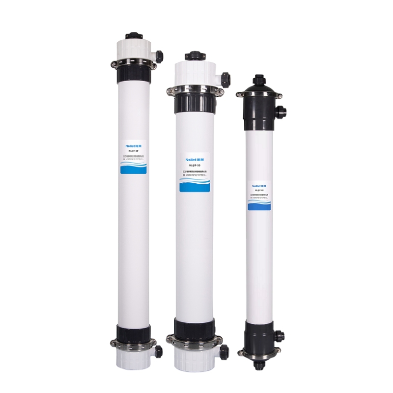
- Hollow Fiber Configurations: Both PVDF and PES are commonly produced in hollow fiber format, available in inside-out (lumen-side feed, suited for lower-turbidity streams) or outside-in (shell-side feed, preferred for high-TSS industrial effluents) flow orientations.
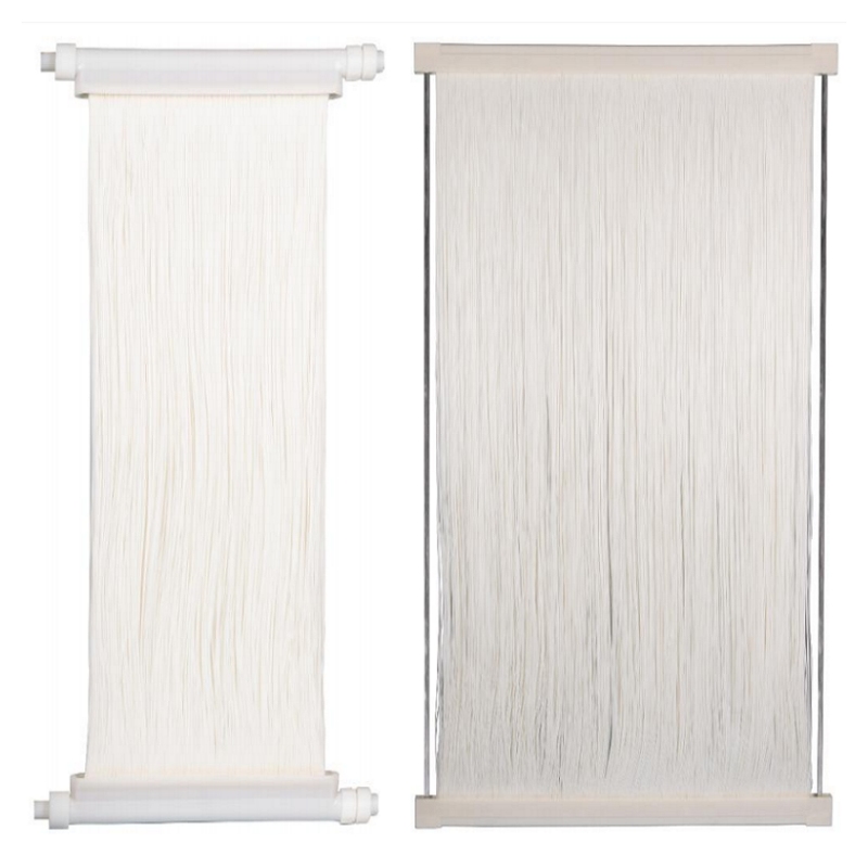
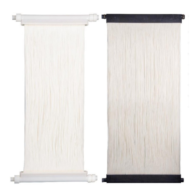
Module formats include pressurized tubular/hollow fiber modules for high-solids industrial streams and submerged flat-sheet or hollow fiber modules for MBR integration. Pressurized systems offer higher flux and easier automation; submerged configurations minimize energy input and footprint in biological treatment trains.
2.2 Operating Parameters & Fouling Control Standards
Sustainable long-term operation requires disciplined fouling management:
- TMP thresholds: Maintain TMP below 0.8–1.5 bar (pressurized) before triggering backwash; sustained TMP creep >20% above baseline signals irreversible fouling onset.
- Backwash protocol: Automated backwash cycles every 20–45 minutes at 1.5–2× operating flux for 30–60 seconds effectively removes reversible cake fouling.
- CIP (Clean-In-Place): Scheduled CIP using NaOH (0.1–0.5%) for organic fouling and citric acid or HCl (0.5–2%) for mineral scaling. CIP frequency depends on feed water quality—high-colloid streams may require weekly maintenance cleans versus monthly recovery cleans for cleaner feeds.
- Recovery rate targets: Well-designed UF systems achieve 90–95% water recovery, with concentrate streams managed through blowdown or further concentration.
Performance validation should reference ASTM E1294 for molecular weight cutoff testing and manufacturer-provided membrane test certificates (MTC) documenting initial flux, rejection coefficients, and integrity test results.
3. Industrial Wastewater Reuse Applications & System Integration
3.1 UF as RO Pretreatment in Zero Liquid Discharge (ZLD) Systems
The most technically demanding application for UF membranes is RO pretreatment within ZLD process chains. RO membranes require feed water with SDI₁₅ ≤ 3 and turbidity <1 NTU to operate within design flux and maintain warranty-compliant fouling rates. Conventional pretreatment—coagulation, flocculation, sand filtration—routinely delivers SDI values of 4–7, creating chronic RO fouling and unplanned maintenance events.
UF membranes reliably produce permeate with SDI₁₅ ≤ 2, providing a consistent, automated pretreatment barrier that decouples RO performance from influent variability. In ZLD systems, the UF stage sits downstream of biological treatment or primary clarification and upstream of the RO train, with the RO concentrate subsequently processed through thermal evaporators or crystallizers.
Key industries deploying UF-RO-ZLD configurations include:
- Power generation: Boiler feed water recovery and cooling tower blowdown reuse
- Semiconductor fabrication: Ultrapure water production from reclaimed process wastewater
- Textile and dyeing: Decolorized effluent reuse after UF/RO polishing
- Municipal water reclamation: Indirect potable reuse (IPR) and non-potable industrial supply
3.2 Direct Reuse Scenarios: Cooling Water, Process Water & Discharge Compliance
Beyond RO pretreatment, UF permeate directly meets quality specifications for several high-volume reuse streams:
- Cooling tower makeup: UF permeate turbidity <0.1 NTU and bacteria-free quality reduces biofouling and chemical dosing requirements in recirculating cooling systems.
- Process wash water: Textile, paper, and food processing industries reuse UF-treated effluent for non-contact process washing, reducing freshwater intake by 30–60%.
- Regulatory discharge compliance: UF effluent consistently meets China GB 18918 Class A reuse standards (turbidity ≤5 NTU, TSS ≤10 mg/L), EU Water Framework Directive Category A reclaimed water quality, and EPA Title 22 tertiary treatment equivalency requirements.
Cost benchmarks for UF-based reuse systems range from USD 0.05–0.20/m³ in operating cost (energy + chemicals + membrane amortization), compared to freshwater procurement costs of USD 0.30–2.00/m³ in water-stressed industrial regions.
4. Commercial & Procurement Considerations
4.1 Total Cost of Ownership: CAPEX vs. OPEX Benchmarks
UF membrane systems carry higher initial CAPEX than conventional media filtration—typically 20–40% premium on equipment cost—but deliver superior OPEX profiles over a 10-year operational horizon:
- Konsumsi energi: 0.1–0.4 kWh/m³ for pressurized UF systems; 0.03–0.1 kWh/m³ for submerged configurations
- Membrane lifespan: 5–10 years under proper operating and cleaning protocols
- Lebih besar, membutuhkan wadah tertutup: UF systems require 40–60% less footprint than equivalent-capacity conventional clarification-filtration trains, reducing civil construction costs
- RO protection value: Extending RO membrane replacement cycles from 2–3 years to 5–7 years through consistent SDI control generates cost savings that typically offset UF CAPEX within 18–36 months
4.2 Supplier Qualification & Procurement Checklist
Procurement teams should validate the following before committing to a UF membrane supplier:
- Membrane Test Certificate (MTC): Confirm factory-tested flux (LMH), rejection rate, and burst pressure for each production lot
- Integrity test protocol: Supplier must provide pressure decay test (PDT) or diffusive airflow test (DAT) procedures and acceptable pass/fail thresholds
- Chemical compatibility data: Request chlorine tolerance (ppm·h), pH operating range, and solvent resistance documentation specific to the membrane polymer
- Warranty terms: Minimum 12-month warranty on membrane integrity; clarify prorated replacement terms for early-life failures
- OEM sourcing risk: Unbranded membranes sourced without MTC documentation carry significant performance variability risk—validate with independent pilot testing before full-scale procurement
- Lead time and inventory: Industrial-grade UF modules typically carry 8–16 week lead times; facilities with critical uptime requirements should maintain 10–15% spare module inventory
FAQ
Q1: What suspended solids concentration can an ultrafiltration membrane reliably handle in industrial wastewater influent?
Most industrial hollow fiber UF membranes are rated for influent TSS up to 200–500 mg/L in pressurized outside-in configurations. For higher-solids streams (500–2,000 mg/L), pre-screening through 100–200 µm drum filters or a primary clarification stage is recommended to protect membrane integrity and maintain sustainable flux. Submerged MBR configurations can tolerate mixed liquor suspended solids (MLSS) up to 8,000–12,000 mg/L within biological treatment.
Q2: How does UF membrane pretreatment extend the service life of downstream reverse osmosis membranes?
RO membrane fouling is predominantly driven by colloidal particles and biological material that accumulate on the membrane surface. By delivering permeate with SDI₁₅ ≤ 2–3 and near-zero turbidity, UF pretreatment reduces RO feed fouling potential by 60–80% compared to conventional pretreatment. This translates directly into extended CIP intervals, lower differential pressure growth rates, and membrane replacement cycles extending from a typical 2–3 years to 5–7 years—representing significant OPEX savings in large RO installations.
Q3: What are the chemical cleaning (CIP) requirements for UF membranes treating high-colloid wastewater streams?
High-colloid streams—common in municipal secondary effluent, food processing wastewater, and paper mill effluent—require more aggressive CIP protocols. Recommended practice includes: weekly maintenance cleans with 0.2–0.5% NaOH at 35–40°C to dissolve organic gel layers, supplemented by monthly recovery cleans alternating between alkaline (NaOH + sodium hypochlorite) and acid (citric acid 1–2%) stages to address mineral scaling. PVDF membranes tolerate the chlorine concentrations required for aggressive biofouling control; PES membranes require chlorine-free alkaline alternatives.
Modul membran terendam merupakan pergeseran paradigma dalam pengolahan air, memberikan hasil unggul dalam skenario yang menuntut tapak kompak, kualitas effluent stabil, penggunaan energi rendah, dan ketahanan fouling yang kuat. Dari sistem MBR kota dan penggunaan ulang air industri hingga produksi air minum dan pengolahan air limbah TPA, modul ini unggul dibandingkan proses konvensional dan teknologi membran bertekanan dalam aplikasi yang paling menantang.
Ultrafiltration membranes deliver a dual commercial value proposition that few single-technology investments can match: they simultaneously enable industrial wastewater reuse and protect the downstream RO assets that anchor ZLD and high-purity water production systems. With quantified removal performance—SDI ≤ 3, turbidity <0.1 NTU, >6-log bacteria rejection—UF membranes provide the consistent effluent quality that conventional clarification cannot guarantee under variable influent conditions.
For procurement engineers, the total cost of ownership calculation is straightforward: UF CAPEX premium is recovered through reduced RO maintenance costs, lower freshwater procurement expenditure, and regulatory compliance assurance within a 24–36 month payback window. Material selection (PVDF for aggressive streams, PES for cleaner feeds), module configuration (pressurized vs. submerged), and rigorous supplier qualification through MTC verification and integrity testing protocols are the three variables that determine whether a UF investment delivers its projected performance over a 7–10 year operational lifecycle.
Ready to specify the right ultrafiltration membrane for your wastewater reuse or RO pretreatment system? Contact our technical team for a process-specific membrane selection consultation, pilot test data review, and detailed total cost of ownership analysis tailored to your facility’s effluent characteristics and reuse targets.