
Overview
- In a drinking water plant, submerged UF replaces the granular media filtration step(or sedimentation plus filtration).
- The retrofit usually lands inside existing filter cells, sedimentation basins, or clearwell compartments. That is often the largest single civil works saving in an upgrade project.
- The dominant risks come from the raw water: seasonal algal blooms, low-temperature low-turbidity conditions, and oxidant dosing that is incompatible with the membrane material -not from sludge.
Why the demand is about upgrading and expanding at once
New-build plants are the minority of projects. Most demand comes from existing plants under three pressures: population or industrial demand growth beyond the original design; tighter finished-water standards, where the conventional coagulation–sedimentation–sand filtration–disinfection train runs out of margin on turbidity, microorganisms, and disinfection by-products; and a site now surrounded by the city, with no land left to expand.
Conventional rapid gravity filters run at roughly 5–8 m/h and are constrained by backwash cycles and media grading. To get more output from the same footprint, you either build more filter area, or you change the separation mechanism. Submerged UF is the second option – and it is also a more definitive answer to the pathogen risk represented by Cryptosporidium and Giardia.
What a submerged UF retrofit actually changes
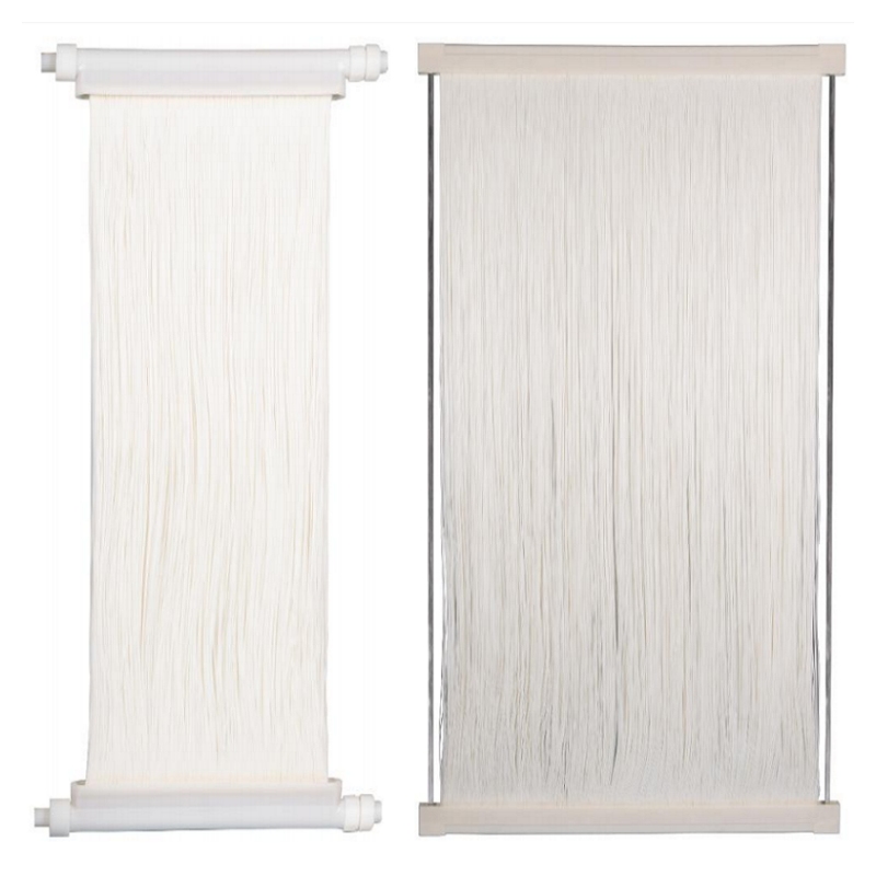
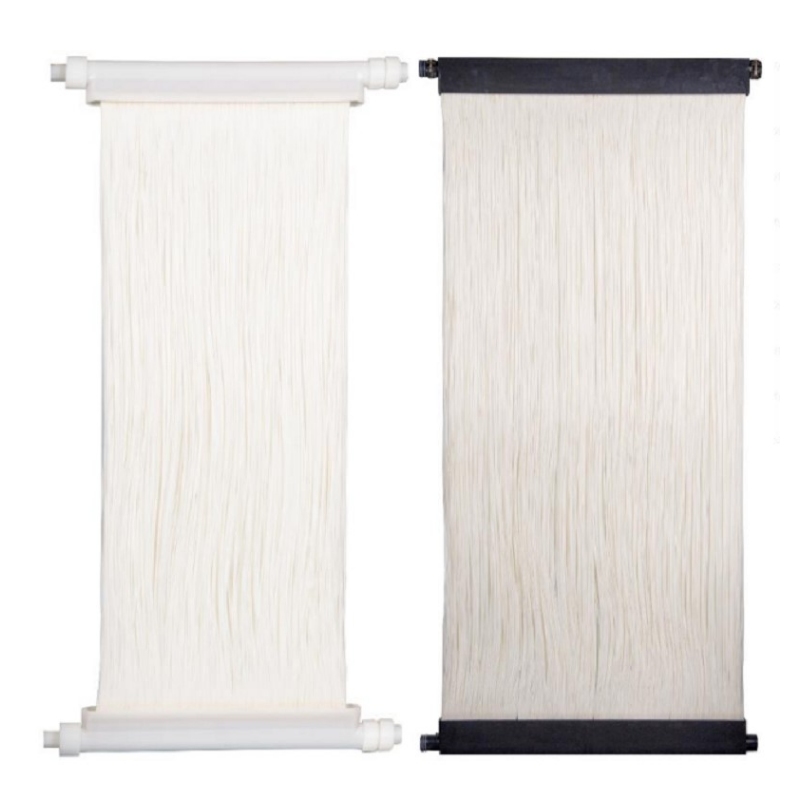
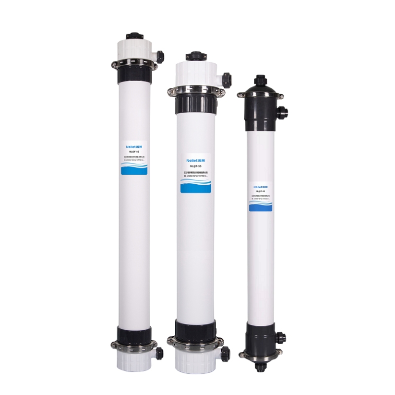
In a submerged configuration, the membrane modules sit directly in the tank water. Permeate is drawn out under a modest vacuum or low pressure, and suspended solids and colloids stay in the basin. Pore size is typically 0.01–0.02 μm – two to three orders of magnitude finer than the capture scale of sand filtration. Two things follow.
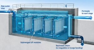
First, filtration precision replaces empirical dependence on media grading. Sand filter effluent turbidity is shaped by raw water variability, backwash performance, and filter bed condition, and it leans heavily on operator judgement. UF effluent turbidity can be held below 0.1 NTU over long periods, with a much weaker correlation to raw water fluctuations. For a plant where turbidity is the key control parameter, that is a step change in controllability.
Second, footprint stops being the constraint. Modules go into existing filter cells or sedimentation basins, turning the civil scope from new-build into retrofit. In dense urban areas, this is often what decides whether a project happens at all.
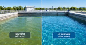
Design Risks in the Retrofitting of UF Membranes at drinking water plants
| Risk | Why it matters | How to address it at design stage |
| Seasonal algal blooms | Algae and their extracellular organics form a dense cake layer that routine backwash cannot recover | Select flux on the peak algal month, not on annual average water quality, and allow adjustment margin in coagulation and pre-oxidation |
| Low temperature, low turbidity | Falling water temperature raises viscosity and TMP at a given flux, so winter output can fall short | Set design flux at the lowest annual water temperature and back-calculate the membrane area from it |
| Oxidant compatibility | Overdosing pre-chlorination, permanganate or ozone accelerates PVDF ageing | Request the allowable oxidant exposure (ppm·h) from the membrane supplier and set a dosing ceiling from it |
| Backwash and concentrate handling | Backwash return flow and turbidity carry-over raise the loading on the coagulation stage, creating a loop | Build a backwash return balance, decide whether it returns upstream of coagulation, and check sludge handling capacity |
| Membrane integrity | Permeate goes straight to consumers – a single breach is a water quality incident, with no downstream disinfection buffer as in a wastewater plant | Online turbidity and particle counting, plus periodic pressure decay testing |
| Pre-treatment interface | Coagulation performance drives the fouling rate, and existing flocculation basins may not suit the new duty | Review coagulant type and dosing points; modify mixing and flocculation stages if needed |
Design flux: where the margin hides
Retrofit projects tend to be proposed at an aggressive design flux, because a higher flux means fewer modules and a lower headline cost. The exposure in a drinking water plant is more concentrated than in a wastewater plant: if low winter temperature and an algal bloom coincide, output falls immediately – and the customer side has no buffer.
The defensible approach is to select design flux at the lowest anticipated water temperature and the highest algal load, and to state the resulting membrane area.
A retrofit checklist
- Survey the existing filter cells or sedimentation basins: actual dimensions, levels, freeboard and structural condition.
- Review coagulation and pre-treatment to confirm they can meet the turbidity and organic load the membranes require.
- Provide data on the lowest water temperature throughout the year and the peak load of algae.
- Clearly define the recovery paths for backwash water and the disposal routes for concentrated water and sludge.
- Provide the raw water quality report.
Next step
If you are evaluating an upgrade or expansion of an existing drinking water plant, send us your basin dimensions, current flow, raw water characteristics and target finished-water standard, and we will propose the required membrane area and configuration.
– Nollet